Reflection
Here we discuss the well-known phenomenon of reflection based on the sum-over-paths method. The approach is illustrated in the Fig. 10 where paths are drawn, along which photon can travel from source to detector. The straight-line segments represent all paths between point source via mirror point to the detector in accord with the analysis in section Point-to-Point paths.
The graph in the lower part of Fig. 10 shows the time, which takes a photon to go from the source to a point on the mirror and then to the detector. In the sum-over-path method the meas-ure for time is the length of the path. Below the mirror there are shown photon vectors after reaching the detector. Sequence summation of these vectors from left to right results in a nice Cornu spiral whose starting and ending points define the vector sum. Square of vector sum length is proportional to a probability that a photon starting from the point source falls onto the detector.

Fig. 10. Reflection on mirror (reflection-mirror.exe)
It is evident; vectors, whose direction is nearly the same, make the major contribution to the vector sum. This happens to be in the vicinity of the least time that a photon needs to land on the detector. By the way we have derived one of the postulates of geometric optic learnt in the elementary school: the angle that an incident ray makes with the normal is equal to the angle that the reflected ray makes to the same normal.
From the Cornu spiral shape one might conclude, that parts of mirror at large distance from the mentioned normal play no role in the reflection phenomenon. Nevertheless, in the section Diffraction it is shown that they play principal role when parts of the mirror are scraped away at regular intervals.
In a television show the question “where has the light gone away when there is dark?” the popular actor Horniček answered, “the light has anywhere gone away, it is only not seen”. Here we confirm the truth of Horniček’s answer by simulation the reflection phenomenon on a slightly thicker sheet of glass. Neglecting rather complex process that takes place in the bulk of glass, we suppose that only the front and the back surfaces reflect light. The probability pattern shown in Fig. 11 takes zero value for some thickness of the glass. That means that for a given monochromatic light there is dark for a detector even thought the source shines with full power.
The computation technique of interference pattern is the same as always. We should repeat the computation process for a mirror reflection, now for the front and the back surfaces of the glass. Nevertheless, we make use of the above got results and we compute the sum only over the paths whose angle of incidence equals to the angle of reflection.
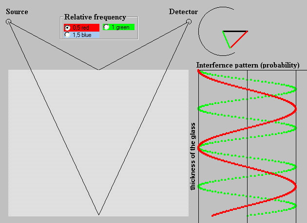
Fig. 11. Double sheet reflection (reflection-double-sheet.exe)
At the top in Fig. 11 the sum (green) of two vectors are shown when a photon reaches the detector. The first of them (black one) is associated with the path that goes via point on the front surface of the glass. It does not change with varying thickness of the glass. The second vector (red one), belonging to the path via point on the back surface, rotates as the glass is getting thicker. Interference pattern for the “red” and the “green” frequencies is shown at the right-hand side in Fig. 11. Due to the above-mentioned neglecting processes in the bulk of glass, the maximum of the patterns does not alter with the frequency.
Now we are going to take into account the scattering of the light in the bulk of glass caused by a collision of photon with electrons, of course in a maximally simplified form. Atoms in glass are scattered randomly, but for the sake of simplicity we suppose that they are aligned in a flat sheets parallel to the glass surface. Their number increases proportionally to the thickness of the glass. Each sheet reflects the photon alike the back surface of glass described above.
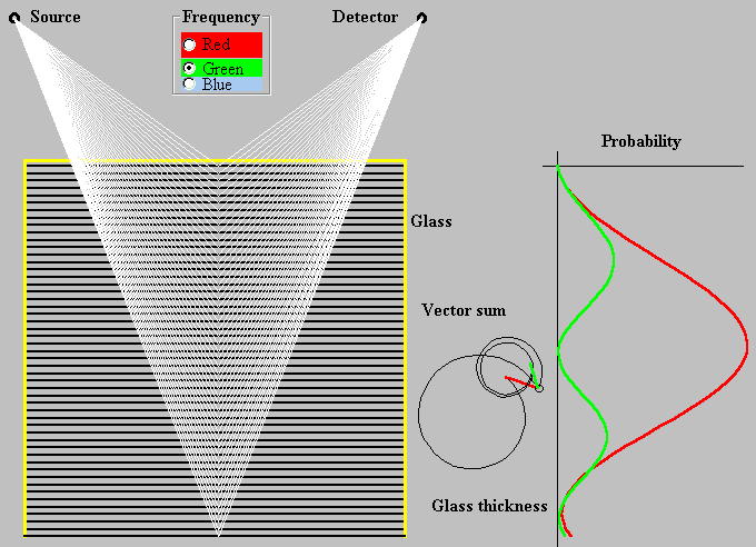
Fig.12. Reflection with scattering in bulk of the thin glass plate (reflection-thin-glass.exe)
The probability of a photon falling onto the detector is shown in Fig. 12. Photon scattering in the bulk of glass causes that the probability maximum is frequency dependent. Photon scattering in the glass (substance) reveals the interference phenomenon that is in specific circumstances referred to as a dispersion, refraction, etc. In the wave theory, these phenomena are associated with a decrease of light speed in substance relative to its velocity in vacuum.