Diffraction
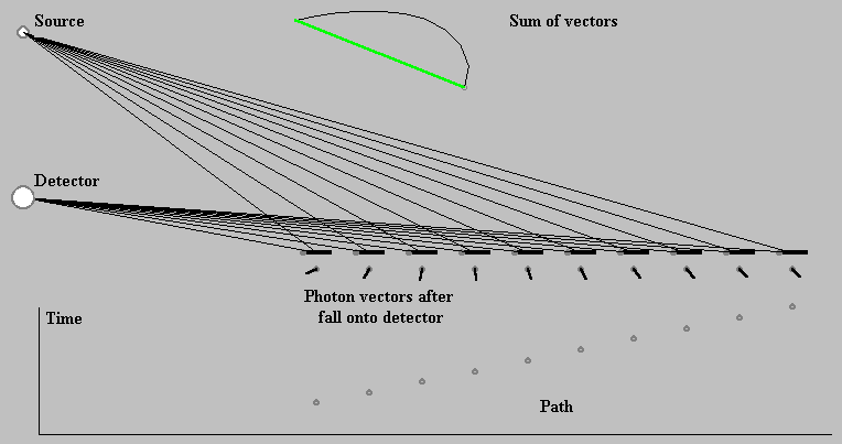
We illustrate the diffraction principles by means of the sum-over-paths method in Fig.8. The detector registers the light of the source if the frequency of the light matches the spacing of reflective pieces in the grating. This matching manifests itself in photon vectors orientation pointing in the mainly same direction for all paths from the source to the detector. The sum of the photon vectors results in a fairly long vector. Its length square indicates the probability that a photon emitted by the source falls onto the detector. In spite of the fact that the photon requires different times for its travel along particular paths, its vector is pointing almost in the same direction for all paths.
For frequencies of the light not matching the grating, the photon vectors are oriented in different directions and the vector sum is short. Alike short resultant vector arises in case that instead of grating an ordinary mirror is reflecting.

Fig. 8. Diffraction grating principle (diffraction-principle.exe)
The interactive program diffraction-grating.exe simulates the diffraction phenomenon in more details (Fig. 9). In this case the grating takes a form of evenly spaced slits in a diaphragm. Depending on the number of the slits the grating is labelled as a double slit, multiple slits (3-4. slits) and a diffraction grating (we have 20 slits in our program). Using the program we can view the forms of interference pattern depending on number of the slits and the frequency of the monochromatic light.

Fig. 9. Diffraction grating (diffraction-grating.exe)
Interference pattern manifests itself in periodically spaced “packages” of high value. Remember that the interference pattern represents the probability that a photon strikes the detector at a given point; it means the illumination intensity. Interference pattern is a kind of picture of the grating. The spacing of the packages is increasing when the light frequency is decreasing.
The diffraction grating, among other technical and scientific applications, is the tool for separating colours in incident light, as is it illustrated by a sketch in the Fig. 9. Equal mixture of red, green and blue lights is an incident at the grating. On a screen opposite the grating, this compound appears to be white. Red component is more separated on the screen than green and blue ones, because the red light has a lower frequency.

Coloured patterns seen on a compact disc (CD) illuminated by sunshine are a product of the diffraction on the grid. Nominal track separation on a CD is 1.6 micrometers. Red light takes wavelengths in the range of 0,6 – 0,74 micrometers and blue light does 0,435 – 0,5 micrometers. Separation of red and blue lights on the CD is several thousand times greater then the track sepa-ration on the CD. The diffraction phenomenon acts this time like a magnifying glass.
The program diffraction-grating.exe enables us to observe an increase (decrease) of the distance D between the interference pattern packages depending on the lower (higher) frequency. Into the program there is not implemented the possibility to change the slits spacing d, as it is possible to achieve all interference pattern forms using the frequency n selection. For the quoted variables is applied a simple relationship D = m/d ν, where m is a constant. This relationship can be easily derived with help of trigonometric relations. However we prefer physical arguments.
Nature, as well as our simulation programs, does not recognise meter or micrometer as a measuring unit. For them the wavelength of light is a natural unit or, speaking in QED language, the distance travelled by photon during one cycle of its frequency ν. With increasing (decreasing) the spacing d we have to decrease (increase) the frequency ν to achieve the unchanged form of the interference pattern.
In the limit case, when d = 0, the grid turns to a wide aperture and the distance D takes an endless value. The diffraction phenomenon is now labelled as aperture diffraction. We can look into its features using the program diffraction-aperture.exe.